|
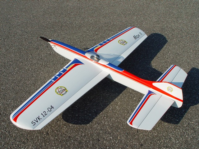
| | The Max II is second version of Max. It also
uses Os Max .46LA with pipe also mounted at 45 deg. and is also mounted directly by screws on
backplate to the firewall.
The model uses my new logaritmic device on flaps. It allows to move CG up to
15% MAC. It gives dead stable straight segments of maneuvers and
lot of feedback to handle in round maneuvers, while still able to make standard
corners, but definitely without waves.
Setup data:
The model is 1550g heavy. It uses 2 blade UCT BE prop 12x3.5. Aero products
Brian Eather
pipe at 400mm glow - first baffle. Carb: 7.2mm i.d. with 3.5mm cross spray bar.
Lap time 5.2s at 10500 t.o. rpm.
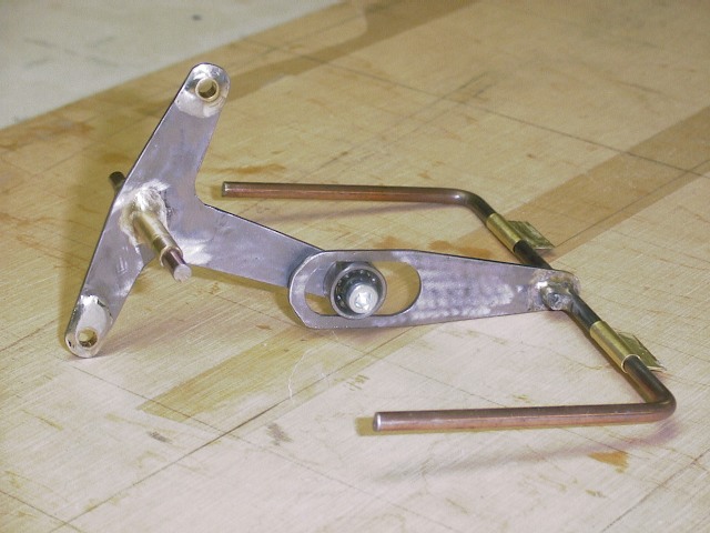
Schema of logharitmic device on flaps
The main idea of the device is in its (almost) LOGARITHMIC
function. It means decreasing character. The device is used on flaps unlike
direct linkage to elevator.
Here is the elevator (x) to flap (y) ratio as used on this
model with the pivot at 55%. Series 1 is 1:1 ratio, series 2 is Logarithmic
device.
The picture shows that flaps go more in range up to 22
degrees, while little less in defleflection 30 degrees in corner (compared to
the elevator). The feedback from flaps to handle is in same ratio, so it is
clear how it works:
1/ Model has nice strong feedback in level and round loops
thanx to more flap deflection around neutral. It stabilizes the model in level
and straight flight. It also makes loops much smoother and pretty round. The
same function makes fly off from corners much better (suppress waves).
2/ 1:1 flap/elevator ratio is not optimal in sharp corners,
so logarithmic device goes till say 27deg in corner instead of 30 in 1:1 ratio.
So the model turns in corner easier itself. It allows to move CG much more to
nose and it gives extra stability. This model has CG at 10% of MAC unlike
similar Max at 19%.
3/ The device carries back much less feedback deflected
than in neutral thanx its function. Thus it needs much less line tension to make
the same corner than same model without it.
4/ The result of point 1/ 2/ and 3/ is model with better
ratio between "turnability" in corner and stability in straight
flight.
Yes, clear there are also disadvantages especially in
construction or life time, but the model has only few flights now, so we will
see later.
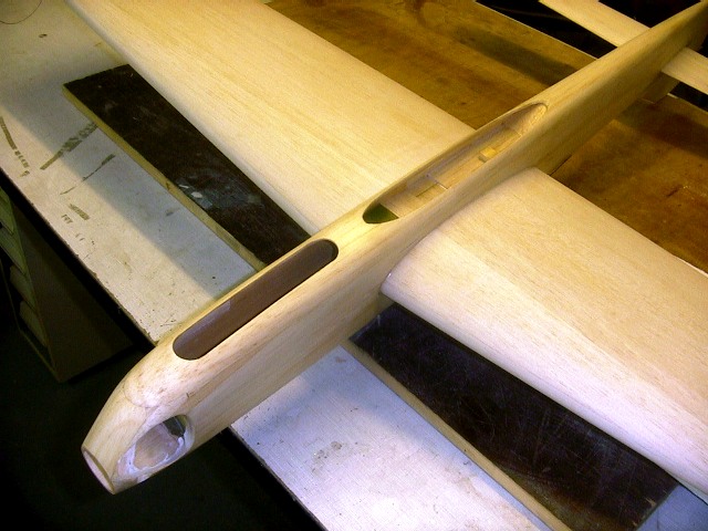
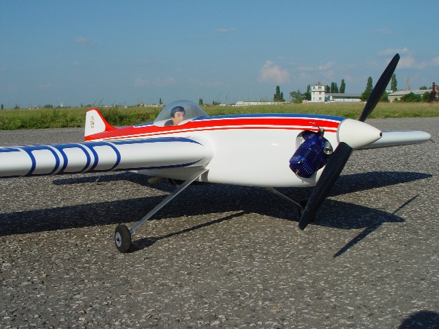
Side view
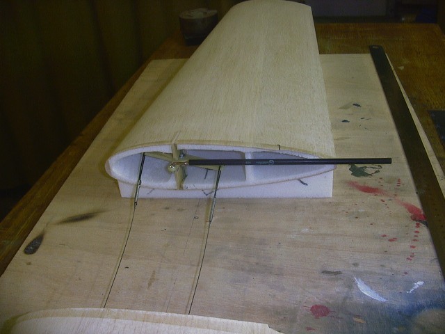
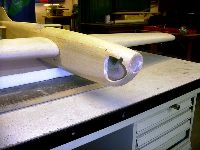
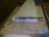
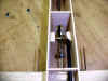
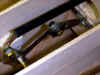
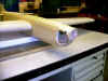
Some pictures from building
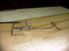
The foam win and bellcrank installation
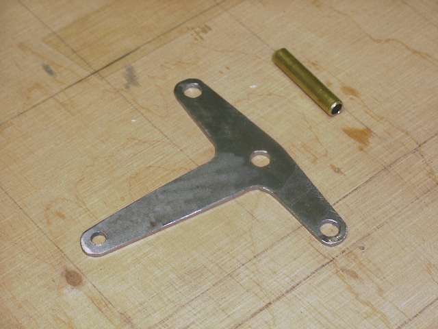
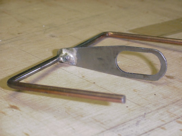
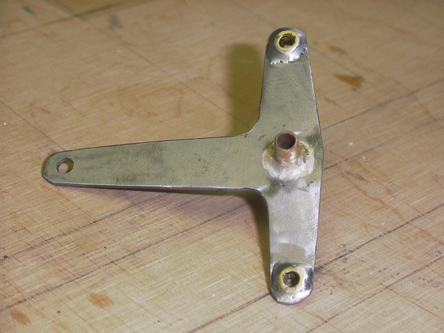
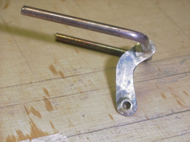
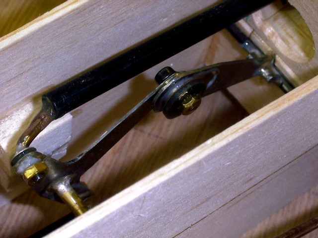
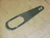
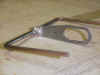
Logarithmic device and its components
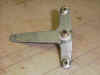 
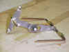
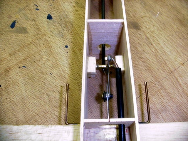
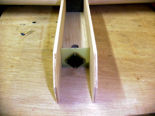
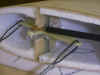
The device installed in fuselage
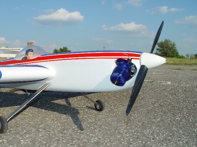
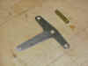
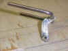
The engine mount

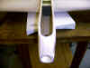 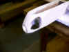

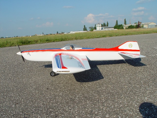
And some pictures
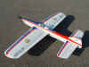
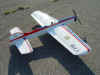
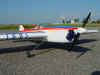
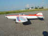 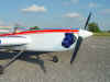
Table of dimmensions:
| wing |
|
|
|
wing |
|
|
| span |
mm |
1500 |
|
area |
m^2 |
0,42 |
| chord root |
mm |
270 |
|
aspect ratio |
|
5,39 |
| chord tip in |
mm |
195 |
|
taper |
|
0,69 |
| chord tip out |
mm |
195 |
|
C/4 sweepback |
deg |
3,76 |
| root flap |
mm |
60 |
|
thickness of airfoil % |
|
0,20 |
| tip flap in |
mm |
30 |
|
area flaps % |
|
0,16 |
| tip flap out |
mm |
34 |
|
max. angle flaps |
deg |
27,19 |
| tip flap to tip |
mm |
30 |
|
wing loading |
kg/m^2 |
3,59 |
| thickness of airfoil
root |
mm |
60 |
|
CG % |
|
10,58 |
| thickness of airfoil tip |
mm |
50 |
|
max. tension flaps pushrod |
N |
43,78 |
|
|
|
|
wing AC offset (level) |
mm |
17,96 |
| tail |
|
|
|
wing AC offset (corner) |
mm |
20,74 |
| span |
mm |
700 |
|
|
|
|
| chord root |
mm |
100 |
|
tail |
|
|
| chord tip |
mm |
75 |
|
area |
m^2 |
0,12 |
| root flap |
mm |
90 |
|
area tail % wing |
|
0,28 |
| tip flap |
mm |
65 |
|
aspect ratio |
|
4,24 |
|
|
|
|
C/4 sweepback |
deg |
2,05 |
| linkage |
|
|
|
taper |
|
0,74 |
| bellcrank max |
deg |
29 |
|
elevator % tail |
|
0,47 |
| bellcrank size |
mm |
100 |
|
max angle tail |
deg |
32,23 |
| bellcrank arm |
mm |
24 |
|
max. tension tail pushrod |
N |
21,94 |
| horn arm flap |
mm |
24 |
|
|
|
|
| horn arm flap/elevator |
mm |
22 |
|
tail/wing C/4 |
|
15,43 |
| horn arm elevator |
mm |
20 |
|
|
|
|
|
|
|
|
necessary line tension |
N |
21,02 |
| lines |
|
|
|
centrifugal force |
N |
47,81 |
| diameter |
mm |
0,36 |
|
line tension over head |
N |
33,11 |
| lenth |
m |
19,5 |
|
drag lines |
N |
2,15 |
| lap time |
s |
5,1 |
|
lines sweepback (level) |
deg |
2,57 |
|
|
|
|
lines sweepback (over head) |
deg |
3,71 |
| prop |
|
|
|
lines to hinge(level) |
mm |
171,32 |
| diameter |
" |
12 |
|
lines to hinge(over head) |
mm |
156,37 |
| pitch |
" |
3,5 |
|
lines leadout to hingeline avg |
mm |
163,84 |
| rpm |
1/min |
11500 |
|
|
|
|
| weight |
g |
20 |
|
speed |
m/s |
25,87 |
|
|
|
|
|
|
|
| fuselage |
|
|
|
power to wingover (mass) |
w |
242,12 |
| prop-wing |
mm |
300 |
|
power to wingover (drag) |
w |
150,59 |
| flap-tail |
mm |
380 |
|
|
|
|
| CG to LE (root) |
mm |
65 |
|
angle of attack prop |
deg |
-2,72 |
| weight |
g |
1500 |
|
|
|
|
| weight of wing ~ |
g |
300 |
|
tip weight (wing asymetry) |
g |
8,30 |
| engine out |
deg |
0 |
|
tip weight (lines/2) |
g |
15,48 |
| engine up |
mm |
22 |
|
tip weight (fuselage) |
g |
17,68 |
| engine down |
deg |
0 |
|
tip weight (sum) |
g |
41,46 |
| fuselage offset right |
mm |
10 |
|
|
|
|
| landing gears height |
mm |
150 |
|
engine out (effective) |
deg |
1,69 |
| wing mass assymetry |
g |
0 |
|
arm of engine out |
mm |
10,74 |
|
|
|
|
arm of engine down |
mm |
22,00 |
| corner radius |
m |
3,50 |
|
|
|
|
|
|
|
|
overall engine momentum (level) (down) |
Nm |
0,00 |
| wing cx level |
|
0,008 |
|
overall engine momentum (corner) (down) |
Nm |
0,08 |
| wing cx corner |
|
0,016 |
|
|
|
|
| tail cx level |
|
0,01 |
|
needed cy wing (corner) |
|
1,80 |
| tail cx corner |
|
0,04 |
|
needed cy tail (corner) |
|
0,52 |
| wing cm corner |
|
0,2 |
|
|
|
|
| tail cm corner |
|
0,15 |
|
speed lost in corner |
m/s |
0,68 |
|
|
|
|
corner recovery (level) |
deg |
0,00 |
| logh. device pivot at |
% |
55 |
|
corner recovery (level) |
m |
0,00 |
|
|
|
|
corner recovery (overhead) |
deg |
0,00 |
|
|
|
|
corner recovery (overhead) |
m |
0,00 |
|
|
|
|
lines retire (level) |
m |
0,00 |
|
|
|
|
lines retire (overhead) |
m |
0,00 |
|
|
|
|
|
|
|
|
|
|
|
angle of attack wing before corner |
deg |
17,36 |
|
|
|
|
angle of attack wing in corner |
deg |
7,21 |
|
|
|
|
reserve of wing cy in corner |
|
0,01 |
|
|
|
|
|
|
|
|
|
|
|
CG front neutral point |
mm |
170,09 |
|
|
|
|
momentum CG to neutral point |
mNm |
90,70 |
|
|
|
|
momentum to mass |
|
6,05 |
|
|
|
|
static reserve of
stability in the circle |
46,51 |
|
|
|
|
static reserve of stability |
% |
28,45 |
|